Why Use the PRO Automatic?
Model AFLB - U.S. Patent No. 8,061,195
In today’s drive to maximize building HVAC hydronic system efficiencies while maintaining flexibility of design, engineers and owners are more often turning to automatic flow limiting devices to achieve those goals.
Automatic flow limiters provide the capability to react to modern, dynamic hydronic systems while preventing overflow at the terminal units. They are ideal for both variable and constant speed pumping systems.
Following our philosophy of “Physics First” designs and lower total cost of ownership, PRO Hydronic Specialties has created and patented the first automatic flow limiting device that can actually measure flow.
Features and Benefits
- Can measure flow
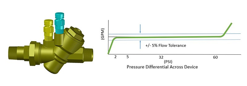
- +/- 5% accuracy rate
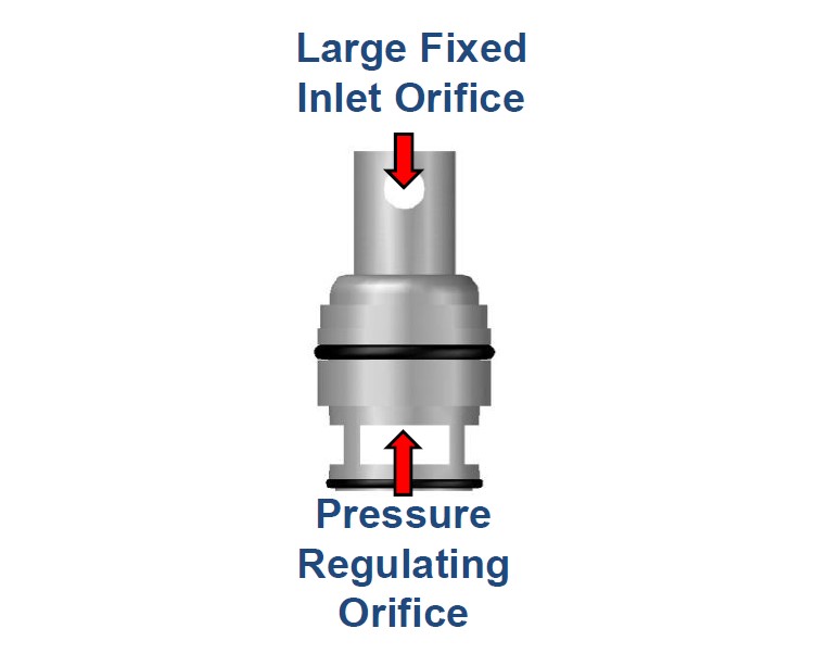
- Large, clog resistant, fixed inlet orifice
- Will not trap debris like a variable orifice
- Constant differential cartridge design
- One spring range (2-60 psid)
- No more spring range selection
- Easy removal (if necessary for flow rate changes)
- Factory secured pre-set flow rate
- Cannot be tampered with in the field
- Stainless steel construction
- No wearable brass or plastic surfaces
Applications
- Water Source Heat Pumps
- Industrial Processes
- Hydronic Heaters
- Unit Ventilators
- Cooling Towers
- VAV HW Coils
- Chilled Beams
- Fan Coil Units
- Air Handlers
- Chillers
Specifications
- Shall have the capability to measure flow. If other designs cannot measure flow with one unit, a separate low energy loss, flow measuring venturi shall be installed on the outlet side of the automatic flow limiter.
- Automatic flow limiting cartridge(s) will be made of stainless steel. No brass or plastic components allowed.
- Flow rate accuracy will be +/- 5% of design flow rate.
- Shall be of a pressure independent, large orifice, clog resistant design.
- Valve cartridge shall have a single spring range of 2-60 psid, up to ASHRAE recommended maximum GPM.
- The flow rate (GPM) shall be factory preset and not field adjustable.
- Cartridge shall be easily removable from valve body without disturbing existing piping.
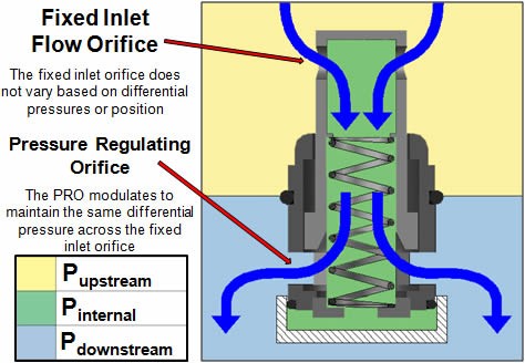
- As system pressures increase, the piston will actuate down seeking an equilibrium point between the force applied to the piston by the upstream pressures and the force internal to the piston applied by compression of the spring along with internal pressures.
- The internal pressure is regulated by the Pressure Regulating Orifice. If the internal pressure increases above the equilibrium point, the orifice opens slightly relieving pressure. The inverse occurs with decreasing pressures.
- This equilibrium maintains a constant differential between the internal pressure of the cartridge and the upstream system pressure.
- Constant differential across a fixed orifice results in constant flow.
Flow Verification Mode
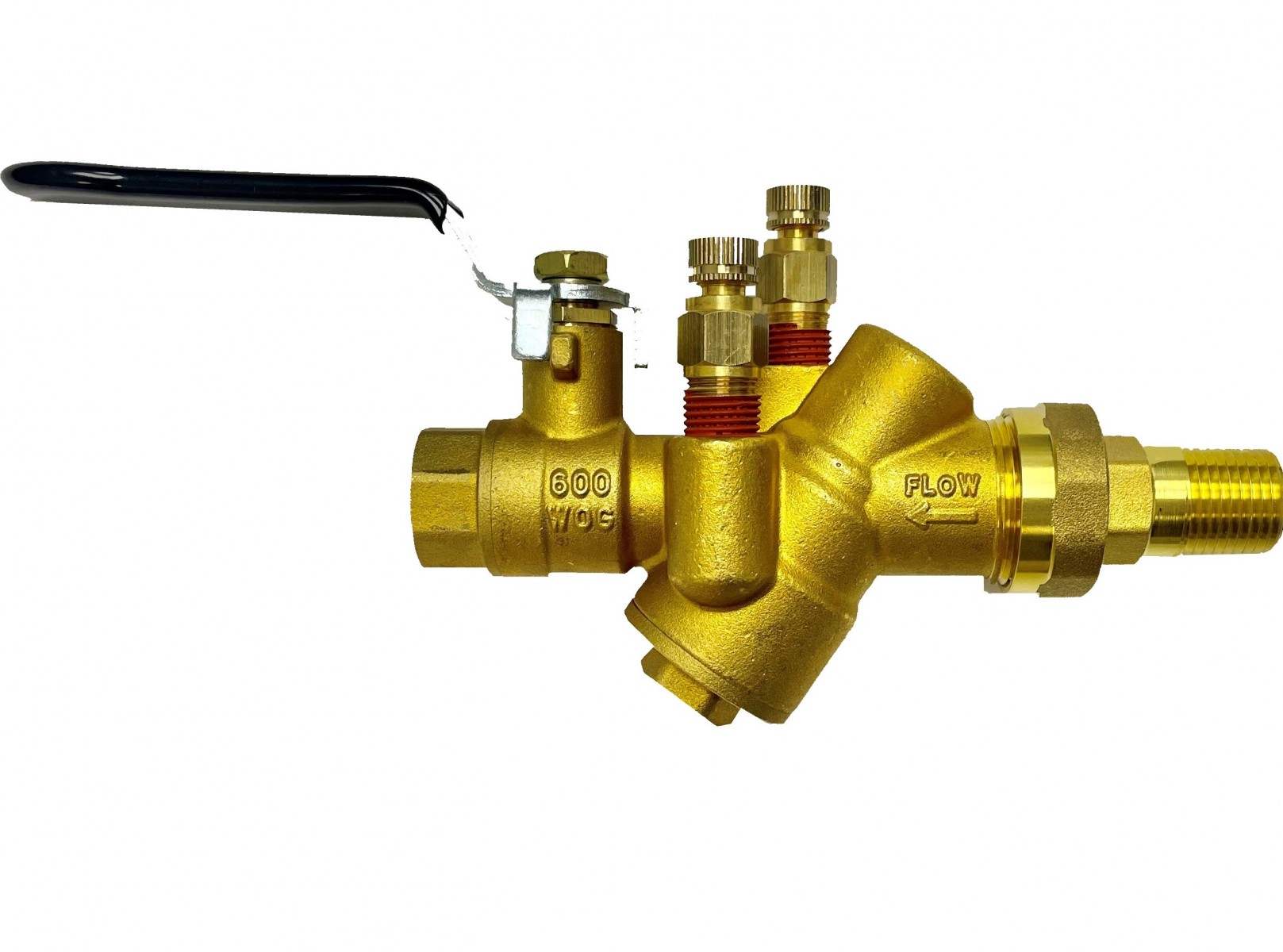
- Place the high side probe into the upstream PT port shown in yellow.
- Place the low side probe into the downstream PT port shown in blue.
- Measure pressure drop in PSI with standard pressure gauges. If pressure drop is between 2-60 PSI then, pressure is verified to be within control range.
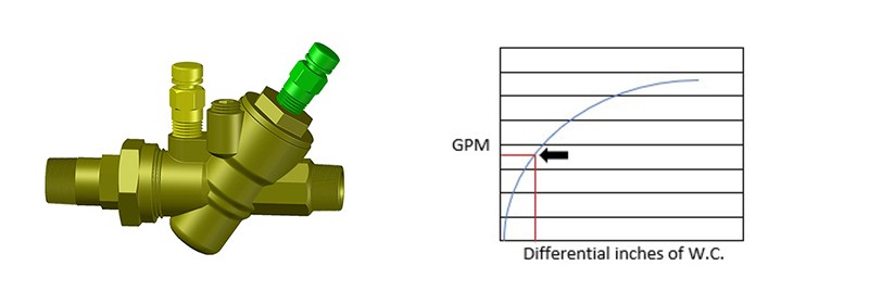
Flow Measurement Mode
- Place the high side probe into the upstream PT port shown in yellow.
- Place the low side probe into the internal PT port shown in green.
- Measure pressure drop in inches of water column using a differential pressure gauge.
- Use the flow table or flow equation provided by PRO Hydronic Specialties to determine flow.